HELIX
Advanced Macro Oscillator
Helix: a digital macro oscillator with 25 algorithms
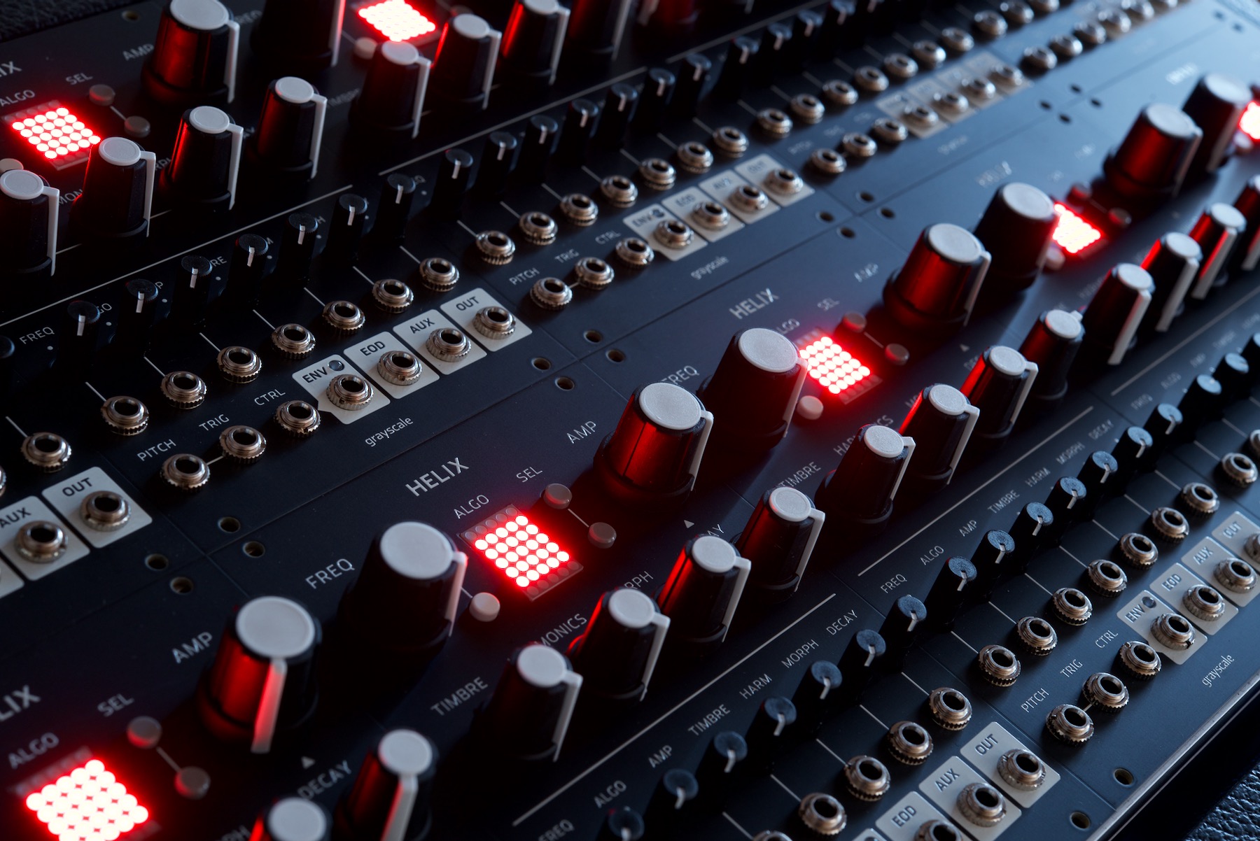
Helix represents the evolution of Mutable's Plaits macro oscillator. With new features such as pitch quantization, parameter randomization, and an internal modulation bus, Helix provides a self-contained synth voice for your Eurorack modular system in an efficient 18hp package.
All 24 algorithms from the final Plaits v1.2 firmware are included, and a new algorithm, the Lo-Fi Oscillator, combines a Buchla-inspired waveshaper with bit rate and sample rate reduction, adding intentional aliasing effects and harmonic distortion. The LED matrix displays all 25 algorithms simultaneously, avoiding the need to switch banks.
The pitch quantizer provides 35 scales, covering both familiar musical territory and obscure microtonal experimentation. Parameter randomization allows all DSP parameters to be randomized whenever a trigger is received. The degree of randomization can be limited and biased for each individual parameter, providing results that range from subtle organic variations to glitchy digital chaos.
Dedicated knobs for the LPG/VCA level and envelope decay time open up new creative possibilities by providing direct access to these previously hidden parameters. The envelope time can be externally modulated and the envelope is now accessible as a modulation source through the new ENV (envelope) and EOD (end of decay) outputs.
The modulation bus, accessed through the CTRL input, allows the internal envelope to be replaced by an arbitrary external control signal. The external modulator is routed to all seven CV inputs simultaneously and may be independently shaped for each parameter using the dedicated attenuators. Because the ENV output remains accessible on the front panel, the internal envelope can still be cross-patched to one or more parameters.
Order Form
Helix is now available. Orders are shipped worldwide via USPS. Shipping costs will be calculated during checkout based on your location. Payment is processed via Paypal.
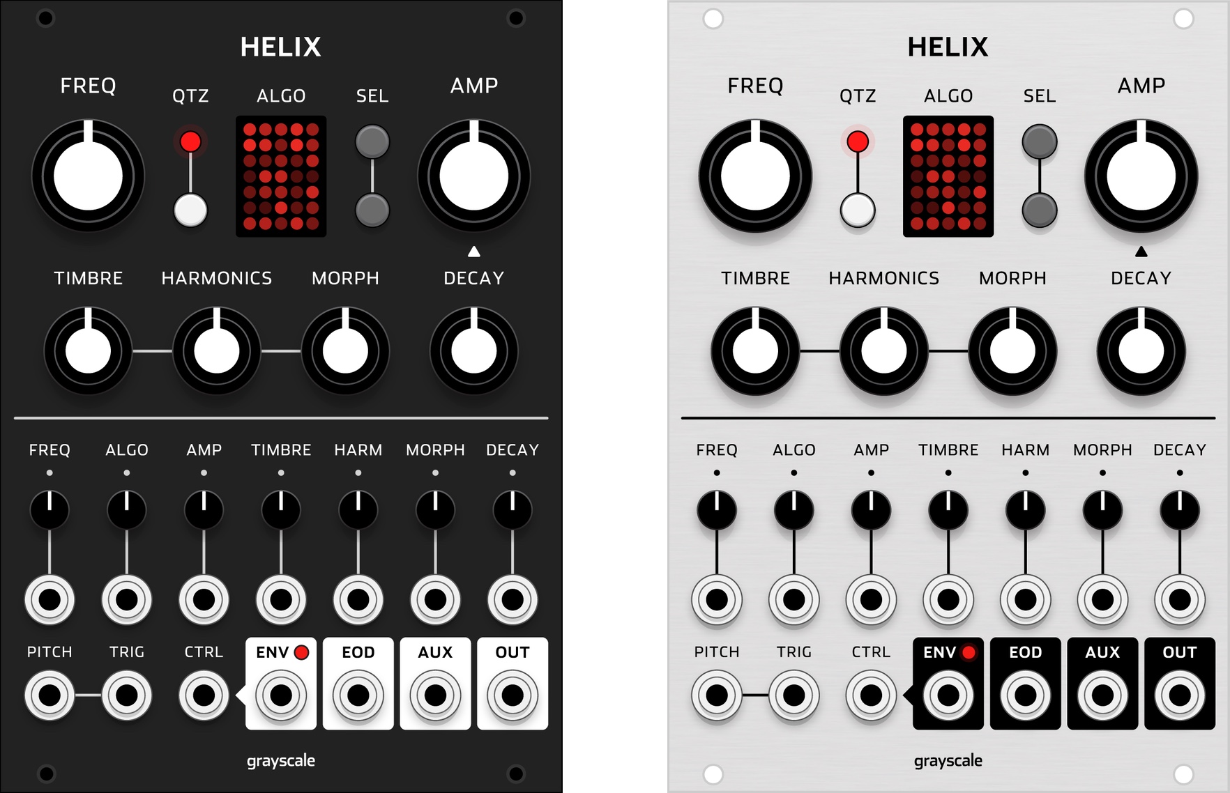
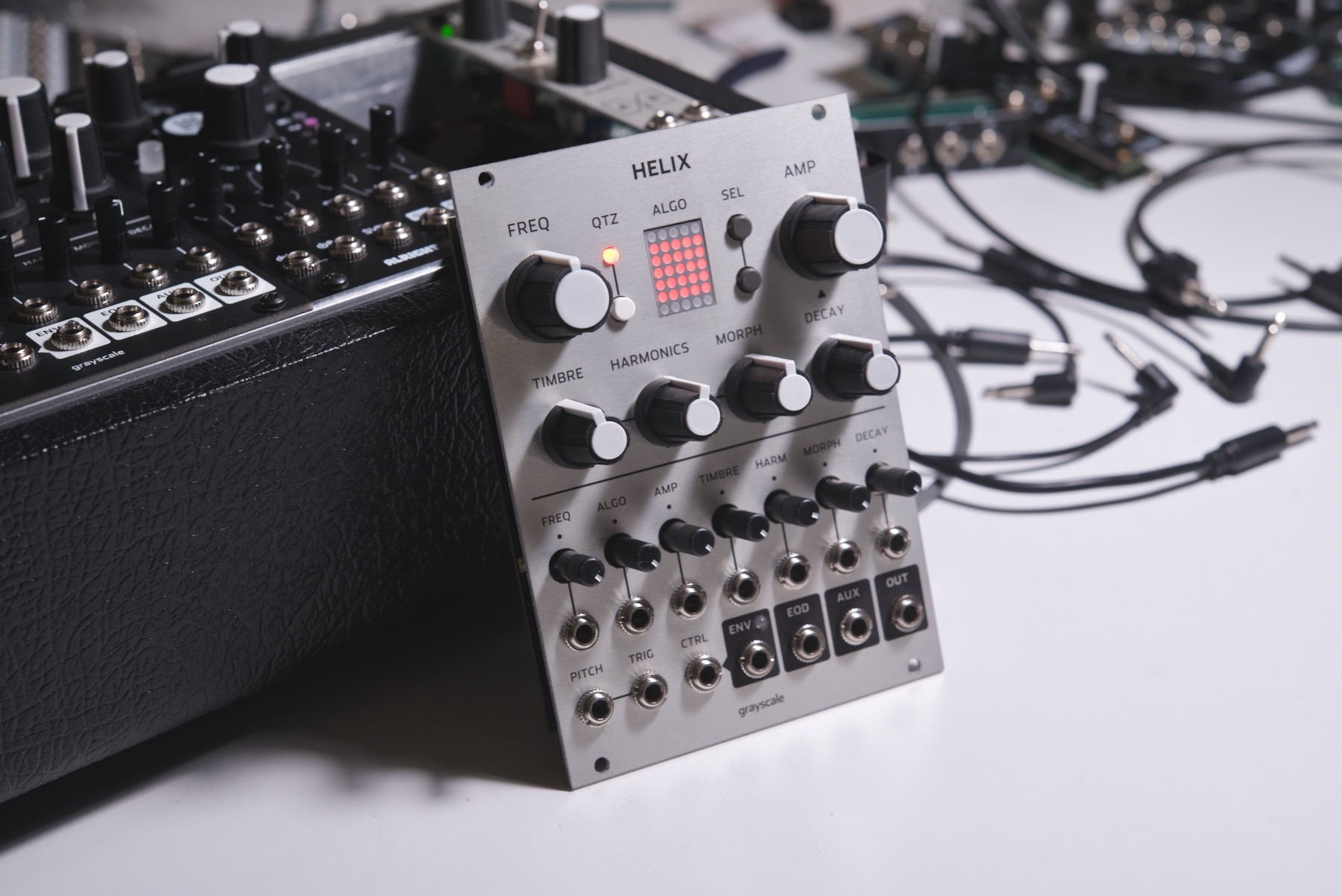
Helix is available with either black (PCB) or gray (aluminum) front panel.
MediaGrayscale Helix Mutable Plaits Audio Video Demos
This intro video briefly describes all of the new features.
This playlist includes demos of all 25 algorithms, some with multiple versions. Left channel is the aux output, right channel is the main output. Recorded at 24 bit / 48 kHz.
Tag @grayscalemodular on Instagram with your videos and they can be embedded here.
Helix vs Plaits
| Attribute | Helix | Plaits |
|---|---|---|
| Width | 18 hp | 12 hp |
| DSP Algorithms | 25 | 24 |
| Display | LED Matrix | 8 LEDs |
| Inputs | 10 | 8 |
| Outputs | 4 | 2 |
| Amplitude and Envelope Decay Knobs | Yes | No |
| Envelope Decay CV Input | Yes | No |
| Envelope and EOD Outputs | Yes | No |
| Modulation Bus (CTRL Input) | Yes | No |
| Pitch Quantizer | Yes | No |
| Parameter Randomization | Yes | No |
| +12V current draw | 70 mA | 50 mA |
| -12V current draw | 11 mA | 5 mA |
User Manual
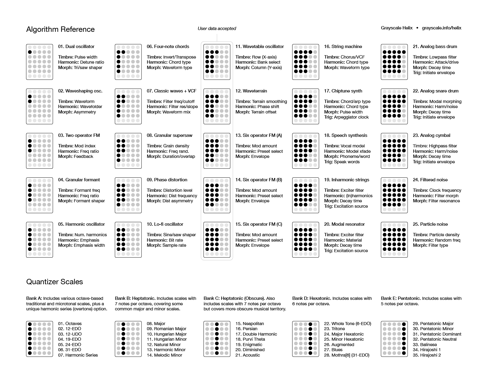
A printable one-page algorithm/quantizer reference can be downloaded below. Refer to the Algorithm Reference and Quantizer Scales for more detailed documentation.
Knobs & Switches
FREQ Knob. Changes the oscillator frequency. The frequency range and root note/octave can also be adjusted, see the Frequency/Pitch Settings section below for details.
QTZ Switch/LED and Pitch Quantizer. Press the QTZ switch to enable/disable the quantizer. After enabling the quantizer, the display will briefly show the currently selected scale. To change the scale, press QTZ for 2 seconds, then use the SEL switches to move up/down through the list of scales. Refer to the Quantizer Scales section for a list of available scales. Certain hidden settings can also be accessed by pressing QTZ while manipulating other knobs and switches.
LED Matrix. By default the 5x7 LED matrix shows a grid representing the 25 DSP algorithms. In other contexts the display shows the grid of quantizer scales, various pitch and amplifier settings, randomization status, and user data upload indicators.
SEL Switches. These switches move up/down through the LED matrix to select different DSP algorithms or quantizer scales. These switches also provide access to various hidden settings when pressed for a certain amount of time or pressing while other manipulating certain knobs and attenuators.
AMP Knob. Controls the level of the LPG/VCA which gates the amplitude of the audio outputs. When the TRIG input is unpatched the AMP knob operates like a simple volume control. When the TRIG input is patched (and the AMP knob is not already turned to its maximum level) the envelope will increase the amplitude level when a trigger is received. See the hidden settings section for instructions on changing the tone of the LPG/VCA.
TIMBRE, HARMONIC, and MORPH Knobs. These three knobs control various aspects of the selected DSP algorithm. Check the Algorithm Reference for further documentation, since the exact parameters vary.
DECAY Knob. Sets the decay time of the internal envelope, from 0-10 seconds. When the TRIG input is patched the envelope will control the amplitude of the LPG/VCA, decaying to the baseline level set by the AMP knob. Try leaving the AMP knob turned up slightly to add a background drone that won't be fully silenced by the envelope.
Inputs and Outputs
CV Inputs and Inverting Attenuators. Each of the 6 DSP parameters, along with the selected algorithm, can be modulated by external CVs. The CV inputs are mapped to a 10Vpp range, from -5V to +5V. With the attenuator centered, external CV will not affect the parameter. Turning to the left will both amplify and invert the external CV. Turning to the right will amplify the external CV without affecting its original polarity. Note that when TRIG is patched the internal envelope is automatically routed to all 7 parameters. Center the attenuators to prevent unwanted modulation. When the CTRL input is patched, the external modulation source will replace the internal envelope, but the attenuation schema works in the same way. See the CTRL Input / Modulation Bus section for more info.
PITCH Input. This is a 1V/octave factory-calibrated pitch CV input with a range of -3V to +7V, covering a range of 10 octaves (slightly more than the FREQ knob). The position of the FREQ knob determines the 0V baseline of CVs patched to the PITCH input.
TRIG Input. Leaving this input unpatched disconnects the internal envelope from the LPG/VCA, so that the AMP knob can function as a simple volume control. Patching the TRIG input engages the internal envelope and allows it to control the LPG/VCA and modulate the other DSP parameters. Some DSP algorithms also require a trigger input to function, or use the trigger for special purposes (such as an arpeggiator clock source). See the Algorithm Reference section for more info.
CTRL Input / Modulation Bus. Patching the CTRL jack disconnects the normalization between the internal envelope and the DSP parameters that it's normally routed to. Want to use a more complex ADSR instead of the internal decay envelope, patch in an LFO, or use a random source? The CTRL bus allows you do to that with a a minimum of patching. The inverting attenuators can be used to shape the CV in the same way. Additionally, patching into any of the individual parameter CV inputs will disconnect the CTRL normalization, allowing some other external CV to be used as a modulator instead. And because the internal envelope remains available at the ENV Out, you can still patch it to one or more parameters while allowing the CTRL signal to modulate any other unpatched CV inputs. (If you've used the Grayscale Supercell, this functionality is very similar to the AUX input, which provides three cascading methods of modulation routing.)
| TRIG Patched | CTRL Patched | Modulation Bus Source |
|---|---|---|
| No | No | None |
| Yes | No | Internal envelope |
| No | Yes | CTRL input (internal envelope not triggered) |
| Yes | Yes | CTRL input (internal envelope remains patchable) |
Note that the FREQ input is a special case, because when unpatched, its attenuator works as a fine-tune control for the oscillator frequency. For the CTRL input to modulate FREQ, the TRIG input must also be patched.
ENV and EOD Outputs. Activated by the TRIG input, this is where the internal envelope can be patched out to control other things in your system. The envelope has a 0-10V range. The decay time is controlled by the DECAY knob and its associated CV input. The maximum decay time is 10 seconds. The EOD output generates a 5ms trigger with an amplitude of 10V each time the envelope finishes its cycle. If the envelope is restarted before finishing its cycle, no trigger will be generated.
AUX and MAIN Outputs. These are the final outputs for the DSP signal path. The AUX output typically generates a secondary signal that complements the MAIN output. Patch both outputs to an external crosssfader or mixer for further processing.
Hidden Settings
These settings don't have dedicated hardware controls, but provide access to deeper layers of functionality.
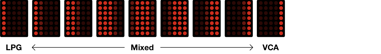
LPG/VCA Tone. The tone of the amplifier can be crossfaded between an LPG (low-pass gate) and a clean VCA. Press the QTZ switch and turn the AMP knob to adjust the tone (left for more LPG, right for more VCA). When the LPG mode is more dominant, the envelope decay progressively filters out the frequency content while also reducing the amplitude. When the VCA mode is more dominant, the envelope has no effect on the frequency content.
Frequency/Pitch Settings. There are three related settings which control the baseline transposition of the oscillator and the behavior of the FREQ knob.
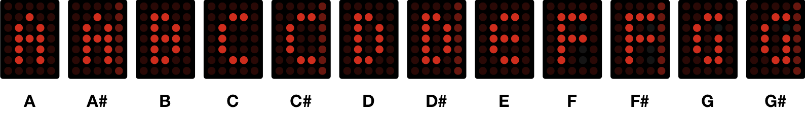
- Root Note: The frequency baseline can be transposed by semitones. Press and hold QTZ and then press either SEL switch to cycle through the semitones in the 12-TET chromatic scale (A through G#). The semitones are constrained to a single octave and do not advance through successive octaves. Illuminated pixels on the right side of the display indicate the five sharp notes (A#, C#, D#, F#, G#).
 Note that the root note does not correspond to an absolute pitch reference, i.e. setting the root note to "A" does not automatically tune the oscillator to multiples of 110 Hz because the final frequency is determined by a combination of the FREQ knob, the FREQ attenuator (which fine-tunes the frequency when the TRIG input is unpatched), and any external CV which might be patched to the PITCH input.
 - Root Octave: The frequency baseline can also be transposed by octaves. Press the lower SEL switch and turn the FREQ knob. The display will indicate the octave baseline, from 0 (all LEDs off) to 7 (top row of LEDs illuminated). This covers a range of 8 octaves. Turn the knob all the way to the left and the display will show "L" which engages LFO mode. In this mode, the Aux and Main outputs generate very low frequencies with a range of about 0.015 Hz (1 minute) to 16 Hz.

- Octave Range: The range of the FREQ knob can be constrained to a certain number of octaves, which allows for finer control of the oscillator frequency. Press the upper SEL switch and turn the FREQ knob. The octave range will be visualized on the display, from 1 octave (all LEDs off) through 8 octaves (all LEDs on).
 This setting interacts with the Root Octave setting. If the Root Octave is set to n (where n = the chosen root octave), the Octave Range accessible by the FREQ knob will necessarily be constrained to 8 minus n, regardless of the Octave Range setting.
Parameter Randomization. Press the lower SEL switch for 2 seconds to see or change the randomization status. The display will either show "R" (on) or "X" (off). Press the upper SEL switch to toggle between these two values, then press the lower SEL switch to exit. The randomization depth and bias can also be adjusted for each parameter.
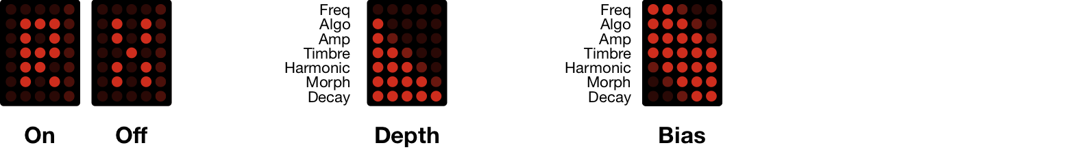
- Randomization Depth: This is a unipolar setting which controls how much the applied randomization will deviate from the values set by the parameter knobs. Press the upper SEL switch and turn any of the 7 attenuators to adjust the randomization depth for the associated parameter. 0% (fully left) means that no randomization will occur, while 100% (fully right) maximizes the randomization depth.
- Randomization Bias: This is a bipolar setting which controls whether randomization is biased towards subtracting from or adding to the baseline values set by the parameter knobs. Press the lower SEL switch and turn any of the 7 attenuators to adjust the bias for the associated parameter. Negative bias (left of center) will tend towards subtraction, while positive bias (right of center) will tend towards addition. With the attenuators turned to the far left or right, the randomization will only be negative or positive. With the attenuator centered, randomization is equally weighted between negative and positive. When randomizing the ALGO parameter, which does not have an associated knob, the current algorithm sets the baseline.
The randomization depth and bias can be reset to their defaults. First, make sure the R/X submenu is active by pressing the lower SEL switch for 2 seconds. The display will either show R or X, depending on whether parameter randomization is engaged. Press the upper SEL switch for 2 more seconds. The display will flash twice to indicate that all 14 of the possible randomization settings have been reset.
User Data Upload. The Wavetable (Algo 11), Waveterrain (Algo 12), and Six Operator FM algorithms (Algo 13-15) accept custom user data, which can be generated using the online Plaits Editor provided by Mutable Instruments. To initiate an upload, first select the algorithm associated with the data type that you want to upload, then press the upper SEL switch for 2 seconds. The display will show "U" to indicate that the module is ready to receive user data. With a 3.5mm cable patched from your computer/phone to the TIMBRE input of Helix, set the device's volume to the maximum level, then play the audio file downloaded from the Plaits Editor. The upload takes about 30 seconds. Progress will be displayed during the upload. If the upload succeeds, the upload UI will exit. If the upload fails, the display will show "E" to indicate an error. Press the upper SEL switch to try again. To exit the upload UI at any time and cancel the upload, press the lower SEL switch. If canceled, the previous data will be retained. However, note that user data uploads are not otherwise persistent. Changing the algorithm or power cycling the module will restore the factory data.
Algorithm Reference
This section covers all 25 Helix algorithms. Additional documentation may be found in the original Plaits user manual (note that the algorithms aren't in the same order).
 Algo 01 |
Dual oscillator. Mix of two analog-style waveforms: a variable-width pulse and a second oscillator which can be continuously waveshaped from a triangle to a glitchy sawtooth. Turn the Timbre knob fully to the left to silence the pulse, or turn the Morph knob fully to the right to silence the tri-saw waveform, taking one or both waveforms out of the mix. The AUX output is the sum of the two waveforms with hard sync applied.
Timbre: Pulse width Harmonic: Relative detuning ratio between waveforms Morph: Tri-to-saw waveshaper |
 Algo 02 |
Waveshaping oscillator. An asymmetric triangle wave is routed through a waveshaper and a wavefolder. The AUX output is similar but uses a different wavefolding method. Both outputs are reminiscent of classic Buchla/Serge wavefolding timbres.
Timbre: Waveshaper waveform Harmonic: Wavefolder amount Morph: Waveform asymmetry |
 Algo 03 |
Two operator FM. Two sine wave oscillators with cross-modulation of phase. The AUX output is a suboscillator derived from the base frequency.
Timbre: Modulation index Harmonic: Frequency ratio Morph: Feedback level/type |
 Algo 04 |
Granular formant oscillator. Simulation of formants using the multiplication, addition, and synchronization of sine wave segments. The AUX output is a simulation of filtered waveforms by windowed sine waves
Timbre: Formant frequency Harmonic: Frequency ratio Morph: Formant width/shape |
 Algo 05 |
Harmonic oscillator. An additive mixture of harmonically-related sine waves. The AUX output uses specific frequency ratios (1, 2, 3, 4, 6, 8, 10, 12) which emulate the drawbars on old organ/string synths.
Timbre: Number of harmonics Harmonic: Central harmonic emphasis Morph: Width of harmonic emphasis |
 Algo 06 |
Four-note chords. Tuned waveforms which emulate vintage string/organ machines with four-note polyphony. The AUX output provides only the root note of the chord.
Timbre: Inversion/Transposition Harmonic: Chord type Morph: Waveform type |
 Algo 07 |
Classic waves with VCF. Morphs between classic analog waveshapes which are passed through a lowpass filter which can be varied from 12dB/octave to 24dB/octave. The AUX output is passed through a fixed-slope 12dB/octave highpass filter.
Timbre: Filter frequency cutoff Harmonic: Filter resonance and slope (12/24 dB) Morph: Waveform and osc/subosc mix |
 Algo 08 |
Granular supersaw. A swarm of 8 enveloped sawtooth waves. The AUX output provides the same but with sine waves. For the classic "supersaw" sound, turn Morph fully to the right and apply subtle CV randomization to the Timbre and Harmonic inputs.
Timbre: Grain density Harmonic: Frequency randomization Morph: Grain duration/overlap |
 Algo 09 |
Phase distortion. A dirty-sounding digital oscillator model based on 1980s digital synthesis techniques. The main outputs use phase distortion (synced carrier wave); the AUX output uses phase modulation (free-running carrier wave).
Timbre: Distortion amount Harmonic: Distortion frequency Morph: Distortion asymmetry |
 Algo 10 |
Lo-fi oscillator. This is a new algorithm unique to Helix which generates crunchy low-fidelity tones with intentional aliasing artifacts and rich harmonics. With Timbre to the left, and Harmonic and Morph to the right, a pure sine wave is generated. As Timbre is turned to the right the sine wave morphs into a sawtooth waveform, adding harmonics. Turning Harmonic and Morph to the left progressively reduces the audio fidelity, generating harsh sidebands and other digital artifacts. The AUX output uses a sine-to-square waveshaper and naive bit/sample rate reduction without anti-aliasing filters for even harsher sounds. Mix the MAIN and AUX outputs together externally for gritty sub-oscillator tones.
Timbre: Sine-to-saw waveshaper Harmonic: Bit rate (approx. 2-12 bits) Morph: Sample rate (approx. 250 Hz - 32 kHz) |
 Algo 11 |
Wavetable oscillator. Four banks of 64 waveforms arranged in an 8x8 matrix. Left of center, the Harmonic knob scans through the four banks with interpolation between waveforms. Right of center, the waveforms are not interpolated. The AUX output is a lo-fi version of the main output with 5-bit resolution, adding extra dirt and noise. The User Data Upload section explains how to upload custom wavetables.
• Bank A: harmonically poor waveforms (additive synthesis) • Bank B: harmonically rich waveforms (formant/waveshaping synthesis) • Bank C: wavetables sampled from vintage synths • Bank D: selected wavetables from banks A-C Timbre: Row index (X-axis) Harmonic: Bank selection Morph: Column index (Y-axis) |
 Algo 12 |
Waveterrain. Uses arbitrary waveforms derived from equations or image uploads, which form 2D waveshapes that resemble landforms. The AUX output provides a different interpretation of the terrain using phase distortion. The User Data Upload section explains how to upload custom waveterrain equations.
Timbre: Terrain smoothing Harmonic: Phase shift Morph: Terrain offset |
 Algo 13 |
Six operator FM (Bank A). The three 6-Operator FM algorithms use the same oscillator model, which emulates the voice structure of the Yamaha DX7. Each bank contains a different collection of 32 DX7 presets.
Bank A contains 32 bass/synth presets. When the TRIG input is patched, triggers will alternate between the two voices, providing two-note polyphony. Modulate the FREQ or PITCH inputs between triggers to create chords. Leaving the TRIG input unpatched results in a monophonic drone. The factory presets for each bank can be replaced. Websites such as Yamaha Black Boxes offer many classic DX7 sysex files for download. The User Data Upload section explains how to upload custom preset banks. Timbre: Modulation amount Harmonic: Preset selection Morph: Envelope and time stretch Trig: Optional (alternates duophonic voices) |
 Algo 14 |
Six operator FM (Bank B). 32 percussive/plucked presets. All other functionality is identical to Bank A.
Timbre: Modulation amount Harmonic: Preset selection Morph: Envelope and time stretch Trig: Optional (alternates duophonic voices) |
 Algo 15 |
Six operator FM (Bank C). 32 sustained presets covering pads, strings, organs, and brass instruments. All other functionality is identical to Bank A.
Timbre: Modulation amount Harmonic: Preset selection Morph: Envelope and time stretch Trig: Optional (alternates duophonic voices) |
 Algo 16 |
String machine. A four-note paraphonic emulation of classic analog string synths, including a chorus effect and stereo filter. The main output predominantly contains the odd voices (1 and 3), while the AUX output predominantly contains the even voices (2 and 4). Mix these outputs externally for an expansive stereo image.
Timbre: Chorus/VCF Harmonic: Chord type Morph: Waveform type |
 Algo 17 |
Chiptune synth with arpeggiator. Generates four-note square wave chords that are reminiscent of 8-bit video game consoles from the 1980s. The AUX output generates a glitchy triangle wave, similar to the one from the 2A03 chip used in the NES. Bonus level: patch a clock to the TRIG input to arpeggiate between the notes of the selected chord.
Timbre: Chord inversion / arpeggiator type Harmonic: Chord type Morph: Pulse width Trig: Optional (clock source for the arpeggiator) |
 Algo 18 |
Speech synthesis. A collection of speech synthesis algorithms. Harmonic selects various speech models including formant filtering, SAM, and LPC vowels, then scans through several banks of LPC words when turned past 11:00. The Morph knob can be used to select words from these banks. Patching the TRIG input will trigger the selected word. The FM attenuator controls intonation and the MORPH attenuator controls speed. The AUX output provides an unfiltered version of the underlying vocalization waveform.
Timbre: Vocalization model Harmonic: Crossfade between different speech models Morph: Phoneme/word selection Trig: Optional (triggers words with certain knob positions) |
 Algo 19 |
Inharmonic strings. Similar to the "red mode" from Mutable's Rings, with three voices of polyphony. This algorithm requires an excitation signal, which may be generated in three different ways. When the TRIG input is unpatched, an internal noise source will randomly trigger the exciter. If the TRIG jack is patched, the exciter will only be triggered when an external pulse is received. Or if an external CV is patched to FREQ or PITCH, changes that exceed a threshold of one semitone (0.08333 volts) will trigger the exciter. The AUX output is the raw excitation signal, which sounds like a short click or noise burst.
Timbre: Exciter filter/brightness Harmonic: (In)harmonics Morph: Decay time Trig: Optional (excitation trigger) |
 Algo 20 |
Modal resonator. Similar to the "green mode" from Mutable's Rings. Monophonic with 24 partials. Like the "Inharmonic strings" algorithm, this algorithm also requires an excitation signal and uses the same triggering logic. The AUX output is the raw excitation signal.
Timbre: Exciter filter/brightness Harmonic: Material selection Morph: Decay time Trig: Optional (excitation trigger) |
 Algo 21 |
Analog bass drum. Percussive model derived from analog hardware simulation. The AUX output provides a bass drum using an alternate DSP model. Patch the TRIG input to trigger individual drum hits.
Timbre: Lowpass filter cutoff Harmonic: Envelope attack + drive Morph: Decay time |
 Algo 22 |
Analog snare drum. Percussive model derived from analog hardware simulation. The AUX output provides a snare drum using an alternate DSP model. Patch the TRIG input to trigger individual drum hits.
Timbre: Modal morphing Harmonic: Harmonic/noise balance Morph: Decay time |
 Algo 23 |
Analog cymbal. Generates metallic tones derived from six square wave oscillators mixed with a noise component, routed through a VCA modeled on a low-fidelity transistor circuit. The AUX output provides an alternate approach using three ring-modulated square waves. Patch the TRIG input to trigger individual drum hits.
Timbre: Highpass filter cutoff Harmonic: Harmonic/noise balance Morph: Decay time |
 Algo 24 |
Filtered noise. Variable-clock white noise processed by a morphing resonant filter. The tuned resonance will properly track CVs applied to the Pitch input. The AUX output uses two bandpass filters whose relationship is controlled by the Harmonic knob.
Timbre: Clock frequency Harmonic: Filter morph (LP>BP>HP) Morph: Filter resonance |
 Algo 25 |
Particle noise. Dust noise processed by networks of all-pass or band-pass filters. The AUX output is the raw noise without processing.
Timbre: Particle density Harmonic: Frequency randomization Morph: Filter type |
Quantizer Scales
Pressing the QTZ switch enables/disables the pitch quantizer. To change the quantizer scale, press QTZ for 2 seconds, then use the SEL switches to step through the scales. Press QTZ again to exit the quantizer menu.
Quantizer scales are organized as five banks of seven related tunings, grouped into columns on the display. The first bank provides octave-based note divisions, including several unconventional tunings based on divisions of the octave, plus an additional quantizer option based on the harmonic overtone series. The second and third banks provide various heptatonic (7-note) musical scales. The fourth bank provides hexatonic (6-note scales) and the 5th bank provides pentatonic (5-note) scales.
When the quantizer is enabled, both the FREQ knob and the PITCH CV input will be quantized to the chosen scale. The FREQ CV input (and its fine-tuning attenuator, if FREQ is unpatched) is not processed by the quantizer and may therefore be used for post-quantizer modulation or transposition. Randomization of FREQ also snaps to quantized values when the quantizer is enabled, allowing for the generation of random sequences which conform to the chosen musical scale.
 Bank A 01-07 |
Bank A: Octave Based / Harmonic01. Octaves: Each increment represents a doubling of the lowest fundamental frequency (as determined by the Root Note). See the Frequency/Pitch Settings above for more info about the Root Note.02. 12-EDO: 12 equal divisions of the octave aka semitone. This is the familiar "black and white keys" chromatic scale. 03. 12-UDO: 12 unequal divisions of the octave, tuned to idealized Pythagorean ratios. This is a type of just intonation tuning which is known for creating more harmonious note intervals than 12-EDO. 04. 19-EDO: 19 equal divisions of the octave, a microtonal tuning system. See this page for a comprehensive look at 19-EDO. 05. 24-EDO: 24 equal divisions of the octave, also called the "quarter tone" scale. Identical to the chromatic scale with one additional tone between each semitone for added dissonance and "blue notes." 06. 31-EDO: 31 equal divisions of the octave, a microtonal tuning system. Watch this video for an excellent overview of 31-EDO. 07. Harmonic Series: Snaps to integer multiples of the fundamental frequency. Try this interactive demo for a useful visualization. |
 Bank B 08-14 |
Bank B: Heptatonic (Major/Minor)This bank provide 7 notes per octave, covering some common major and minor scales. 08. Major09. Romanian Major 10. Hungarian Major 11. Hungarian Minor 12. Natural Minor 13. Harmonic Minor 14. Melodic Minor |
 Bank C 15-21 |
Bank C: Heptatonic (Obscure)This bank also provide 7 notes per octave but covers some more obscure musical territory. 15. Neapolitan16. Persian 17. Double Harmonic 18. Purvi Theta 19. Enigmatic 20. Diminished 21. Acoustic |
 Bank D 22-28 |
Bank D: HexatonicThis bank includes scales with 6 notes per octave. 22. Whole Tone (6-EDO)23. Tritone 24. Major Hexatonic 25. Minor Hexatonic 26. Augmented 27. Blues 28. Mothra[6], a supermajor hexatonic scale from 31-EDO |
 Bank E 29-35 |
Bank E: PentatonicThis bank includes scales with 5 notes per octave. 29. Pentatonic Major (Diatonic)30. Pentatonic Minor 31. Pentatonic Dominant 32. Pentatonic Neutral 33. Balinese 34. Hirajoshi 1 35. Hirajoshi 2 |
